By Allen Houtz1 and Doug Cooper
The ratio control architecture is used to maintain the flow rate of one stream in a process at a defined or specified proportion relative to that of another. A common application for ratio control is to combine or blend two feed streams to produce a mixed flow with a desired composition or physical property. Consistent with other articles in this e-book, applications of interest are processes with streams comprised of gases, liquids, powders, slurries or melts.
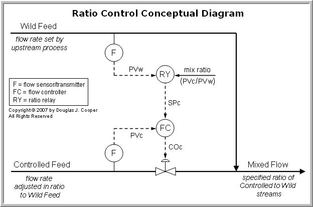
The conceptual diagram below (click for a large view) shows that the flow rate of one of the streams feeding the mixed flow, designated as the wild feed, can change freely. Its flow rate might change based on product demand, maintenance limitations, feedstock variations, energy availability, the actions of another controller in the plant, or it may simply be that this is the stream we are least willing to manipulate during normal operation.
The other stream shown feeding the mixed flow is designated as the controlled feed. A final control element (FCE) in the controlled feed stream receives and reacts to the controller output signal, COc, from the ratio control architecture. While the conceptual diagrams in this article show a valve as the FCE, we note that other flow manipulation devices such as variable speed pumps or compressors may also be used in ratio control implementations.
Relays in the Ratio Architecture
As the above diagram illustrates, we measure the flow rate of the wild feed and pass the signal to a relay, designated as RY in the diagram. The relay is typically one of two types:
▪ A ratio relay, where the mix ratio is entered once during configuration and is generally not available to operations staff during normal operation.
▪ A multiplying relay (shown), where the mix ratio is presented as an adjustable parameter on the operations display and is thus more readily accessible for change.
In either case, the relay multiplies the measured flow rate of the wild feed stream, PVw, by the entered mix ratio to arrive at a desired or set point value, SPc, for the controlled feed stream. A flow controller then regulates the controlled feed flow rate to this SPc, resulting in a mixed flow stream of specified proportions between the controlled and wild streams.
Linear Flow Signals Required
A ratio controller architecture as described above requires that the signal from each flow sensor/transmitter change linearly with flow rate. Thus, the signals from the wild stream process variable, PVw, and the controlled stream process variable, PVc, should increase and decrease in a straight-line fashion as the individual flow rates increase and decrease.
Turbine flow meters and certain other sensors can provide a signal that changes linearly with flow rate. Unfortunately, a host of popular flow sensors, including inferential head flow elements such as orifice meters, do not. Additional computations (function blocks) must then be included between the sensor and the ratio relay to transform the nonlinear signal into the required linear flow-to-signal relationship.
Flow Fraction (Ratio) Controller
A classic example of ratio control is the blending of an additive into a process stream. As shown below (click for a large view), an octane booster is blended with straight-run gasoline stream being produced by an atmospheric distillation column. For any number of reasons, the production rate of straight-run gasoline will vary over time in a refinery. Therefore, the amount of octane booster required to produce the desired octane rating in the mixed product flow must also vary in a coordinated fashion.
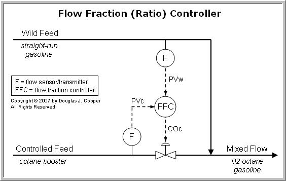
Rather than using a relay, we present an alternative ratio control architecture based on a flow fraction controller (FFC). The FFC is essentially a “pure” ratio controller in that it receives the wild feed and controlled feed signals directly as inputs. A ratio set point value is entered into the FCC, along with tuning parameters and other values required for any controller implementation.
Ratio Relay or Flow Fraction Controller
The flow fraction (ratio) controller is a preconfigured option in many modern computer based DCS or advanced PLC control systems. It provides exactly the same functionality as the ratio relay combined with a single-input single-output controller as discussed above.
The choice of using a relay or an FFC is a practical matter. The entered ratio multiplier value in a relay is not a readily accessible parameter. It therefore requires a greater level of permission and access to adjust. Consequently, the use of the ratio relay has the advantage (or disadvantage depending on the application) of requiring a higher level of authorization before a change can be made to the ratio multiplier.
Multiplying Relay With Remote Input
The ratio controller shown below (click for a large view) presents an additional level of complexity in that, like the cascade architecture, our ratio controller is contained within and is thus part of a larger control strategy.
In the example below, an analyzer sensor measures the composition or property we seek to maintain in the mixed flow stream. The measured value is compared to a set point value, SPA, and a mix ratio controller output signal, COA, is generated based on the difference. Thus, like a cascade, the outer analyzer controller continually sends mix ratio updates to the inner ratio control architecture.

The updated mix ratio COA value enters the multiplying relay as an external set point. The objective of this additional complexity is to correct for any unmeasured changes in the wild feed or controlled feed, thus maintaining the mixed flow composition or property at the set point value, SPA.
The term “analyzer” is used broadly here. Hopefully, we can indentify a fast, inexpensive and reliable sensor that allows us to infer the mixed flow composition or property of interest. Examples might include a capacitance probe, an in-line viscometer, or a pH meter.
If we are required to use a chromatograph, spectrometer or other such instrument, we must allow for the increased maintenance and attention such devices often demand. Perhaps more important, the time to complete a sample and analysis cycle for these devices can introduce a long dead time into our feedback loop. As dead time increases, best attainable control performance decreases.
____
1. Allen D. Houtz
Consulting Engineer
Automation Systems Group
P.O. Box 884
Kenai, AK 99611
Email: ifadh@uaa.alaska.edu