By Allen Houtz1 and Doug Cooper
We explored override control using select elements in a previous article and learned that environmental and energy efficiency concerns for metered-air combustion processes can be partially addressed with a single select override element. Examples illustrated how a select override can either prevent having too much fuel or too much air in the air/fuel mixture fed to the burner of a combustion process, but one override element alone is not capable of preventing both scenarios.
In this article we explore the addition of a second select override element to create a cross-limiting architecture that prevents the air/fuel ratio fed to the burner from becoming overly rich (too much fuel) or lean (too much air) as operating conditions change. Variations on this cross-limiting architecture are widely employed within the air/fuel ratio logic of a broad range of industrial combustion control systems.
Steam Boiler Process Example
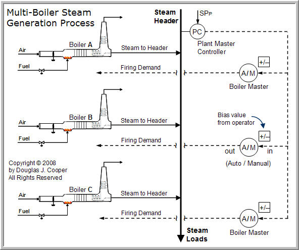
To provide a larger context for this topic, we begin by considering a multi-boiler steam generation process as shown below (click for a larger view):
Steam generation processes often have multiple boilers that feed a common steam header. When steam is needed anywhere in the plant, the load is drawn from this common header. Steam turbines, for example, drive generators, pumps and compressors. Steam is widely used for process heating, can be injected into production vessels to serve as a reactant or diluent, and may even be used to draw a vacuum in a vessel via jet ejectors.
With so many uses, steam loads can vary significantly and unpredictably over time in a plant. The individual boilers must generate and feed steam to the common header at a rate that matches these steam load draws. Controlling the steam header to a constant pressure provides an important stabilizing influence to plant-wide operation.
- Plant Master Controller
A popular multi-boiler architecture for maintaining header pressure is to use a single pressure controller on the common header that outputs a firing demand signal for all of the boilers in the steam plant. This steam header pressure controller is widely referred to as thePlant Master.
Based on the difference between the set point (SPP) and measured pressure in the header, the Plant Master controller computes a firing demand output that signals all of the boilers in the plant to increase or decrease firing, and thus, steam production.
- Boiler Master Controller
The Boiler Masters in the above multi-boiler process diagram are Auto/Manual selector stations with biasing (+/–) values. If all three of the Boiler Masters are in automatic, any change in the Plant Master output signal will pass through and create an associated change in the firing demand for the three boilers.
If a Boiler Master is in automatic, that boiler is said to be operating as a swing boiler. As such, its firing demand signal will vary (or swing) directly as the Plant Master signal varies. If each of the fuel flow meters are scaled so that 100% of fuel flow produces maximum rated steam output, then each boiler will swing the same amount as the Plant Master calls for variations in steam production.
But suppose Boiler B has cracked refractory brick in the fire box or some other mechanical issue that, until repaired, requires that it be operated no higher than, for example, 85% of its design steam production rate. That is, Boiler B has been derated and its maximum permissible steam generating capacity has been lowered from the original design rating. Two options we can consider include:
| 1. | When a Boiler Master is in automatic, then: signal out = signal in + bias where the bias value is set by the operator. If the bias value of Boiler Master B is set in this example to –15%, then no matter what output is received from the Plant Master (0% to 100%), the firing demand signal will never exceed 85% (100% plus the negative 15% bias). In this mode of operation, Boiler B will still swing with Boiler A and Boiler C in response to the Plant Master, but it will operate at a firing rate 15% below the level of the other two boilers (assuming their bias values are zero). |
| 2. | If a boiler is suffering from refractory problems, then allowing the firing rate to swing can accelerate refractory degradation. Thus, Boiler Master B might alternatively be switched to manual mode where the output firing demand signal is set to a constant value. In manual mode, Boiler B is said to provide a base load of steam production. With the firing rate of Boiler B set manually from the Boiler Master, it is unresponsive to firing demand signal variations from the Plant Master. We then would have two swing boilers (Boiler A and Boiler C) and one base loaded boiler (Boiler B). |
Combustion Control Process
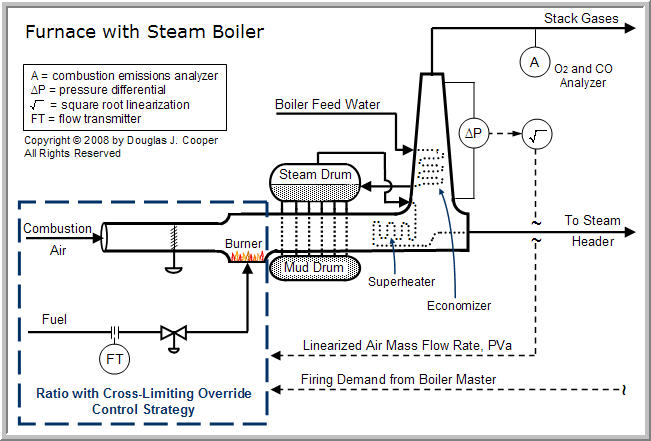
As shown below (click for a larger view), each furnace and steam boiler has its own control system. Of particular interest here is the maintenance of a specified air/fuel mass ratio for efficient combustion at the burners.
As shown above, the air/fuel ratio control strategy receives a firing demand from the Boiler Master. Air mass flow rate may be measured downstream of the combustion zone and is thus shown as an input to the ratio control strategy.
The boiler feed water and steam drum level controls are not discussed here but can be found in this 3-Element Level Control article.
Ratio with Cross-Limiting Override Control
Certain assumption are used in the presentation that follows:
| 1. | Air/fuel ratio is normally expressed as a mass flow ratio of air to fuel. |
| 2. | The air and fuel flow transmitter signals are linear with respect to the mass flow rate and have been scaled to range from 0-100%. |
| 3. | The flow transmitters have been carefully calibrated so that both signals at the design air/fuel ratio are one to one. That is, if the fuel flow transmitter signal, PVf, is 80%, then an air flow signal, PVa, of 80% will produce an air flow rate that meets the design air/fuel mass ratio. This enables us to implement the ratio strategy without using multiplying relays as discussed at the end of this article. |
Shown below (click for a larger view) are the sensors, controllers, final control elements (FCEs) and function blocks that might be included in the above dashed box labeled “ratio with cross-limiting override control strategy.”
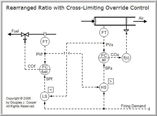
Before discussing the details of the strategy, we rearrange the loop layout to make the symmetry of the design more apparent (click for a larger view). Specifically, we reverse the fuel flow direction (fuel now flows from right to left below) and show the air mass flow rate transmitter as a generic measurement within the control architecture. The control diagram above is otherwise identical to that below.
| Practitioner’s Note: In any real process, different flow loops will have different process gains (the same change in controller output signal, CO, will produce a different change in flow rate) and each loop itself will display a nonlinear behavior over its range of operation (the process gain, time constant and/or dead time will change as operating level changes). The purpose of the characterizing function block, f(x), is to match the process gain of one loop over the range of operation with that of the other loop. With matching signal-to-flow gains, this optional function block simplifies the tuning of a ratio control strategy with two flow control loops. The characterizing function block, f(x), also simplifies manual operation because the two flow CO signals will be approximately equal at the design air/fuel ratio. |
As shown above, the firing demand signal enters the high select override as a candidate for the set point of the air flow controller (SPa). In this cross-limiting strategy, the same firing demand signal enters the low select override as a candidate for the set point of the fuel flow controller (SPf).
As discussed in assumption 3 above, the flow transmitters have been calibrated so that when both signals match, we are at the design air/fuel mass flow ratio. Thus, because of the high select override, SPa is always the greater of the the firing demand signal or the value that matches the current fuel flow signal. And because of the low select override, SPf is always the lesser of the firing demand signal or the value that matches the current air flow signal.
The result is that if firing demand moves up, the high select will pass the firing demand signal through as SPa, causing the air flow to increase. Because of the low select override, the fuel set point, SPf, will not match the firing demand signal increase, but rather, will follow the increasing air flow rate as it responds upward.
And if the firing demand moves down, the low select will pass the firing demand signal through as SPf, causing the fuel flow to decrease. Because of the high select override, the air set point, SPa, will not match the firing demand signal decrease, but rather, will track the decreasing fuel flow rate as it moves downward.
In short, the control system ensures that during sudden operational changes that move us in either direction from the design air/fuel ratio, the burner will temporarily receive extra air until balance is restored (we will be temporarily lean). While a lean air/fuel ratio means we are heating extra air that then goes up and out the stack, it avoids the environmentally harmful emission of carbon monoxide and unburned fuel.
Variable Air/Fuel Ratio
The basic cross-limiting strategy we have described to this point provides no means for adjusting the air/fuel ratio. This may be necessary, for example, if the composition of our fuel changes, if the burner performance changes due to corrosion or fouling, or if the operating characteristics of the burner change as firing level changes.
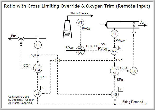
Shown below (click for a larger view) is a cross-limiting override control strategy that also automatically adjusts the air/fuel ratio based on the oxygen level measured in the exhaust stack.
As shown in the diagram, the signal from the air flow transmitter, PVraw, is multiplied by the output of the analyzer controller, COO2, and the product is forwarded as the measured air flow rate process variable, PVa.
With this construction, if the measured exhaust oxygen, PVO2, matches the oxygen set point, SPO2, then the analyzer controller (AC) output, COO2 will equal one and PVa will equal PVraw.
But if the oxygen level in the stack is too high, COO2 will become greater than one. By multiplying the raw air flow signal, PVraw, by a number greater than one, PVa appears to read high. And if the oxygen level in the stack is too low, we multiply PVraw with a number smaller than one so that PVa appears to read low.
The ratio strategy reacts based on the artificial PV values, adjusting the air/fuel ratio until the measured oxygen level, PVO2, is at set point SP02.
This manipulation to the air/fuel ratio based on measured exhaust oxygen is commonly called oxygen trim control. By essentially changing the effective calibration of the air flow transmitter to a new range, the signal ratio of the carefully scaled air and fuel transmitters can remain 1:1.
| Practitioner’s Note: Analyzers fail more often than other components in the strategy, so when designing and tuning the analyzer controller, it is important to limit how far COO2 can move from its baseline value of one. Also, the analyzer controller is effectively the primary (outer) controller in a cascade loop. The secondary (inner) loop is the same air flow control loop being driven by the Plant Master. As a result, it is advisable to tune the oxygen (or combustibles) trim controller significantly more conservatively than the Plant Master to minimize loop interactions. |
____
1. Allen D. Houtz
Consulting Engineer
Automation Systems Group
P.O. Box 884
Kenai, AK 99611
Email: ifadh@uaa.alaska.edu