By Allen D. Houtz 1
One common application of cascade control combined with feed forward control is in level control systems for boiler steam drums.
The control strategies now used in modern industrial boiler systems had their beginnings on shipboard steam propulsion boilers. When boilers operated at low pressure, it was reasonably inexpensive to make the steam drum large. In a large drum, liquid level moves relatively slowly in response to disturbances (it has a long time constant). Therefore, manual or automatic adjustment of the feedwater valve in response to liquid level variations was an effective control strategy.
But as boiler operating pressures have increased over the years, the cost of building and installing large steam drums forced the reduction of the drum size for a given steam production capacity.
The consequence of smaller drum size is an attendant reduction in process time constants, or the speed with which important process variables can change. Smaller time constants mean upsets must be addressed more quickly, and this has led to the development of increasingly sophisticated control strategies.
3 Element Strategy
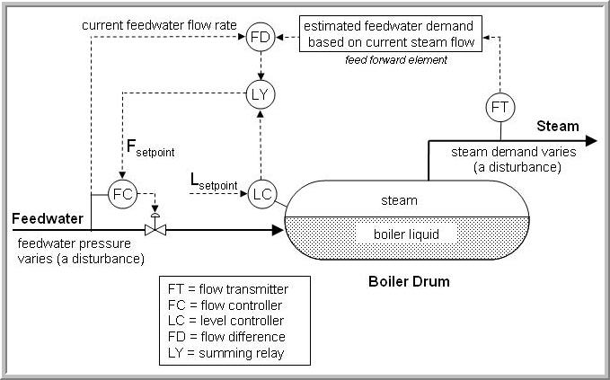
As shown below (click for large view), most boilers of medium to high pressure today use a “3-element” boiler control strategy. The term “3-element control” refers to the number of process variables (PVs) that are measured to effect control of the boiler feedwater control valve. These measured PVs are:
▪ liquid level in the boiler drum,
▪ flow of feedwater to the boiler drum, and
▪ flow of steam leaving the boiler drum.
Maintaining liquid level in the boiler steam drum is the highest priority. It is critical that the liquid level remain low enough to guarantee that there is adequate disengaging volume above the liquid, and high enough to assure that there is water present in every steam generating tube in the boiler. These requirements typically result in a narrow range in which the liquid level must be maintained.
The feedwater used to maintain liquid level in industrial boilers often comes from multiple sources and is brought up to steam drum pressure by pumps operating in parallel. With multiple sources and multiple pumps, the supply pressure of the feedwater will change over time. Every time supply pressure changes, the flow rate through the valve, even if it remains fixed in position, is immediately affected.
So, for example, if the boiler drum liquid level is low, the level controller will call for an increase in feedwater flow. But consider that if at this moment, the feedwater supply pressure were to drop. The level controller could be opening the valve, yet the falling supply pressure could actually cause a decreased flow through the valve and into the drum.
Thus, it is not enough for the level controller to directly open or close the valve. Rather, it must decide whether it needs more or less feed flow to the boiler drum. The level controller transmits its target flow as a set point to a flow controller. The flow controller then decides how much to open or close the valve as supply pressure swings to meet the set point target.
This is a “2-element” (boiler liquid level to feedwater flow rate) cascade control strategy. By placing this feedwater flow rate in a fast flow control loop, the flow controller will immediately sense any variations in the supply conditions which produce a change in feedwater flow. The flow controller will adjust the boiler feedwater valve position to restore the flow to its set point before the boiler drum liquid level is even affected. The level controller is the primary controller (sometimes referred to as the master controller) in this cascade, adjusting the set point of the flow controller, which is the secondary controller (sometimes identified as the slave controller).
The third element in a “3-element control” system is the flow of steam leaving the steam drum. The variation in demand from the steam header is the most common disturbance to the boiler level control system in an industrial steam system.
By measuring the steam flow, the magnitude of demand changes can be used as a feed forward signal to the level control system. The feed forward signal can be added into the output of the level controller to adjust the flow control loop set point, or can be added into the output of the flow control loop to directly manipulate the boiler feedwater control valve. The majority of boiler level control systems add the feed forward signal into the level controller output to the secondary (feedwater flow) controller set point. This approach eliminates the need for characterizing the feed forward signal to match the control valve characteristic.
Actual boiler level control schemes do not feed the steam flow signal forward directly. Instead, the difference between the outlet steam flow and the inlet water flow is calculated. The difference value is directly added to the set point signal to the feedwater flow controller. Therefore, if the steam flow out of the boiler is suddenly increased by the start up of a turbine, for example, the set point to the feedwater flow controller is increased by exactly the amount of the measured steam flow increase.
Simple material balance considerations suggest that if the two flow meters are exactly accurate, the flow change produced by the flow control loop will make up exactly enough water to maintain the level without producing a significant upset to the level control loop. Similarly, a sudden drop in steam demand caused by the trip of a significant turbine load will produce an exactly matching drop in feedwater flow to the steam drum without producing any significant disturbance to the boiler steam drum level control.
Of course, there are losses from the boiler that are not measured by the steam production meter. The most common of these are boiler blow down and steam vents (including relief valves) ahead of the steam production meter. In addition, boiler operating conditions that alter the total volume of water in the boiler cannot be corrected by the feed forward control strategy. For example, forced circulation boilers may have steam generating sections that are placed out of service or in service intermittently. The level controller itself must correct for these unmeasured disturbances using the normal feedback control algorithm.
Notes on Firing Control Systems
In general, firing control is accomplished with a Plant Master that monitors the pressure of the main steam header and modulates the firing rate (and hence, the steam production rate) of one or more boilers delivering steam to the steam header. The firing demand signal is sent to all boilers in parallel, but each boiler is provided with a Boiler Master to allow the Plant Master demand signal to be overridden or biased. When the signal is overridden, the steam production rate of the boiler is set manually by the operator, and the boiler is said to be base-loaded. Most boilers on a given header must be allowed to be driven by the Plant Master to maintain pressure control. Boilers that have the Boiler Master set in automatic mode (passing the steam demand from the Plant Master to the boiler firing control system) are said to be swing boilers as opposed to base-loaded boilers.
The presence of heat recovery steam boilers on a steam header raises new control issues because the steam production rate is primarily controlled by the horsepower demand placed on the gas turbine providing the heat to the boiler. If the heat recovery boiler operates at a pressure above the header pressure, a separate pressure control system can be used to blow off excess steam from the heat recovery boiler when production is above the steam header demand. Note that for maximum efficiency, most heat recovery boilers are fitted with duct burners to provide additional heat to the boiler. The duct burner is controlled with a Boiler Master like any other swing boiler. As long as there are other large swing boilers connected to the steam header, the other fired boilers can reduce firing as required when output increases from the heat recovery boiler.
____
1. Allen D. Houtz
Consulting Engineer
Automation System Group
P.O. Box 884
Kenai, AK 99611
Email: ifadh@uaa.alaska.edu